


Substrate Transfer
The goal with automated substrate transfer is simple. Without the use of human locomotion, a substrate should make its way from a parked location (in a load lock or within the chamber itself on a specialized stage), to the stage in the process module, ready for the deposition process.
Substrate transfer is achieved using an automated transfer arm. The movement of the arm is controlled using a closed loop controller with position feedback response (servomotor) that allows for precise control of position, velocity, and arm acceleration.
Positioning and precision are carefully considered in the design and execution of this type of automation, as the goal is to save time and increase efficiency. If a substrate carrier, or a sample itself were to be dropped or hit another component in the system, time would be wasted. For this reason, Angstrom Engineering employs a number of strategies to create a reliable and safe process to automatically transfer both substrates and their accompanying masks (if required).
The position of the stage (the substrate’s end goal) is determined and accurately controlled using a closed-loop controller, or an AC motor controlled by Aeres®. Its position is controlled using proximity sensors.
Above: This video demonstrates an automatic transfer on a system that also happens to employ a variable angle stage.
In the case of a single or dual process module system, the transfer sequence occurs in the following manner: first, the transfer arm moves from its parked position into a load lock, it picks up a substrate carrier from a vertically mobile substrate/mask cassette. This is command generated through the Aeres® control software using position identifiers on both the substrate carrier and the cassette. The arm then moves into the process module (the deposition chamber) through an open gate valve, mounts it on the stage using pneumatic clamps, and finally backs out of the process module, through the load lock, and back to its original position. This process is demonstrated in the short video on this page.
Transfer arms are not all made equal. Angstrom Engineering’s standard transfer arm is created the full length of its required reach, requiring the system to have a wide form factor, and sufficient space in the lab for its entire length. It is possible, however, to save space by telescoping the arm, as is the case with two Amod PVD platforms you can see to the left (or below for mobile).
In the case of the Nebula Cluster system, a different transfer process is involved. For more information, click here:
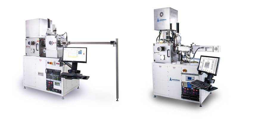
Above: Two Amod PVD Platforms. On the left, a standard transfer arm. On the right, a telescoping transfer arm.
Give us a call
An email works too! Let’s discuss what would be best for your system.
We look forward to connecting with you about your work.
Angstrom Engineering has worked to make their equipment highly functional, but not overly complex to use. Whenever I call I get immediate assistance. In an extremely busy facility like Princeton’s MNFL, these qualities have made Angstrom my first choice for PVD tools.
Joe Palmer – MNFL – Princeton University